Pipeline Integrity, Safety, Structural health Monitoring and leak detection with the Fiber Optic Sensor system

Distributed fiber optic sensing is tested through practice technology for online monitoring of temperature, strain, vibration, and sound over long distances with the high local resolution that is apt to improve pipeline integrity, pipeline safety, and security considerations. Fiber optics distributed temperature sensing techniques have found applications in various domains such as civil engineering, oil, and gas, power plants, fire detection, etc.

Pipelines are the most modern, effective, and reliable global transport systems for oil, gas, and water. In order to guarantee the smooth transport of products the pipeline systems must be regularly maintained and monitoring. Optical sensing systems today facilitate pipeline monitoring and integrity as preventive means to continuously protect or monitor pipelines. The systems are based on interferometric sensing where ultra-stable, low noise lasers interrogate an optical fiber acting as one long continuous sensor embedded or attached to the pipeline. The monitoring of temperature profiles over long distances by means of optical fibers represents a highly efficient way to fiber optic leak detection along pipelines, in dams, dikes, or tanks. Different techniques have been developed taking advantage of the fiber geometry and of optical time-domain analysis for the localization of the information.

Distributed temperature sensing is used in all cases to improve the performance of computational monitoring systems. Although distributed temperature sensing is a well-proven technology that has shown to be able to detect very small leaks in a short time, it is very hard to calculate the minimum detectable leak size or to guarantee a maximum detection time which in many cases are necessary to receive pipeline operation licenses. Leak rates as low as 50 ml/min have been detected on a brine pipeline by temperature monitoring and identification of local temperature anomalies.

GeoHazards like earthquakes, landslides, and surface subsidence result in ground movement and thus put additional stress on the pipelines, tunnels, and other underground infrastructures. Structural health monitoring is a promising and challenging field of research in the 21st century. Civil structures are the most precious economic assets of any country, proper monitoring of these are necessary to prevent any hazardous situation and ensuring safety. Fiber Bragg Grating (FBG) sensors have emerged as a reliable, in situ, nondestructive device for monitoring, diagnostics, and control in civil structures. FBG sensors offer several key advantages over other technologies in the structural sensing field.

The transformer is the key equipment in a power system, to ensure its safe and stable operation is important. Transformers either raise a voltage to decrease losses or decreases the voltage to a safe level. The failures of transformers in service are broadly due to temperature rise, low oil levels, overload, poor quality of LT cables, and improper installation and maintenance. Out of these factors temperature rise, low oil levels and overload, need continuous monitoring to save transformer life. A DTS system increases the reliability of the distribution network, by monitoring critical information such as oil temperature, and the oil level of the transformer. Data are collected continuously. Monitoring the transformers for problems before they occur can prevent faults that are costly to fix and result in a loss of service life. With modern technology, it is possible to monitor a large number of parameters of a transformer monitoring system at a relatively high cost. At the present day, the challenge is to balance the functions of the monitoring system and its cost and reliability. 

Phase-shifted fiber Bragg gratings (πFBGs)

Phase-shifted FBGs
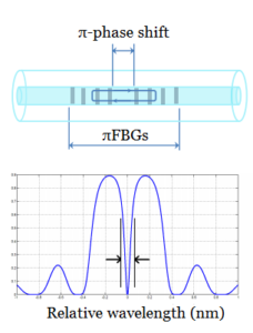
Nowadays, the special type of FBGs whose reflection spectrum has a notch arise from a π-phase discontinuity in the center of the grating (called π-phase-shifted FBGs) attracts ground interests among researchers. Because of their highly sensitive ultrasonic detection, πFBG may provide a solution to the sensitivity problems of the FBG. By introducing a π- phase shift into a refractive index modulation of the fiber Bragg grating during its fabrication, the spectral transmission has a narrow bandpass resonance appearing within the middle of the reflection lobe of the FBG. Such an element allows reaching a very narrow transmission band of few picometers.

Fabrication of π-phase-shifted FBGs is achieved by splitting the standard FBG into two identical sub-FBGs with a half-period phase difference between them. The two sub FBGs create an interfere with each other and generate an ultra-narrow transmission window at the center of the FBG spectrum.

Due to the phase discontinuity, a πFBG can be conceptually described as a Fabry–Perot cavity formed by two FBG mirrors. When the two FBGs are highly reflective, the quality factor of the Fabry–Perot cavity is increased, leading to an extremely narrow spectral notch for highly sensitive ultrasonic detection.

Using special structures, even multiple transmission bands are possible.

The primary method used for the fabrication of π-Phase-shifted fiber Bragg grating is based on the UV laser and phase mask method. The occurrence of two peaks/dips is attributed to the refractive index modulations along with the fiber core, with the periodicity of the π-phase mask that has been observed previously in images of gratings that cause destructive interference in a reflected wave at the Bragg condition owing to the phase difference between the grating phases. Thus, the standard phase mask technique produced an alternative type of pi-phase-shifted grating at twice the design Bragg wavelength.

The phase-shifted gratings have found application in distributed feedback lasers, wavelength division multiplexing, athermal setup, or temperature stabilization, as well as to a tuning setup. Also, the π-phase-shifted FBG can be used in highly accurate wavelength references, ASE filtering, spectroscopy, and optical CDMA.


Chirped Fiber Bragg Gratings (CFBG) for high-speed fiber optic communications systems

A chirp is a linear variation in the grating period, that can be added to the refractive index profile of the grating. The reflected wavelength fluctuates with the grating period, broadening the reflected spectrum. A grating possessing a chirp has the ability to add dispersion—especially, different wavelengths reflected from the grating will be subject to different delays.

A non-uniform resonance wavelength along the length of the grating in a CFBG can be accomplished by varying the period or by varying the average effective refractive index. The average refractive index can be changed using different methods, for example, changing the amplitude of the reflective index modulation profile or variation the fiber in the region of the grating length. The chirped FBG was manufactured with the usage of a chirped phase mask to generate a variation in the period of the refractive index.

Chirped fiber Bragg gratings have been widely used for dispersion compensations in high-speed fiber optic communications systems because they are able to retard pulsed light depending on its wavelength. Experience has proven that ideas in one field find applications in another. Actually, this type of optical device has been attracting significant attention in the fiber optic sensing community, in high sensitivity sensors or wavelength discriminators in interrogation systems.

There are two prevailing fields of application of chirped FBG: measurement of curvature based on chirped fiber Bragg gratings and new interrogation system, written in an Erbium-doped fiber. The increasing demand for measurement of curvatures has stimulated the appearance of few sensing systems that depend on the intrinsic characteristics of fiber Bragg gratings. A curvature measurement technique using a smart composite consists of two chirped fiber Bragg gratings. The two gratings are embedded on the opposite sides of the composite laminate and serve as curvature sensors and as wavelength discriminators enabling a temperature-independent intensity-based scheme for the measurement of the radius of curvature.

FBG interrogation relies on the usage of the edge filtering concept applied to a chirped fiber Bragg grating written in an erbium-doped fiber as the processing element. Through the combination of the photon amplification of the erbium-doped fiber and of the distributed wavelength reflection characteristics of the chirped FBG, it becomes possible to reach different reading sensitivities and amplification of the remote sensing signal. The ability of chirped FBG has also been employed successfully in the development of interrogation techniques. One of these techniques uses the group-delay in a Sagnac loop interferometer and another the spectra response of broadband chirped gratings.

Tilted FBG – optical Fiber Bragg Gratings (TFBG)

Tilted FBGsThe tilted FBG is a new kind of sensor that includes all the advantages of established usage Bragg grating technology in addition to being able to excite cladding modes resonantly. This device opens possibilities for single-point sensing in hard-to-reach places.

Tilted fiber Bragg gratings are also known as slanted gratings or blazed gratings. This is a special type of short-term optical fiber gratings. TFBGs are fabricated using the same tools and techniques as standard FBGs, i. e. from a permanent refractive index change induced in doped glasses by an interference pattern between two intense ultraviolet laser beams. The boundary surface of the varied index is not vertical with respect to the fiber axis but has a certain angle. One feature of tilted FBG is that they can couple guided modes with copropagating modes or counterpropagating modes in specific wavelengths.

As we have known that tilted FBG can unite light from guided modes into radiation modes or cladding modes. The cladding modes are investigated theoretically by studying a three-layer model of optical fibers, whereas the core mode is investigated by studying a two-layer model of optical fibers. The analysis reveals that to increase the coupling of the energy transferred from the core mode to cladding modes, the cladding radius needs to be decreased. Such behavior is illustrated by studying the change in the electric field distribution and is used to enhance the sensitivity of the sensing refractive index of the surrounding medium.

Connection efficiency with the help of tilted FBGis sensitive to light polarization, various sensors, and devices based on these characteristics have been proposed or developed for a wide range of applications. TFBG sensors are using for mechanical and biochemical applications, including one-dimensional TFBG vibroscopes, accelerometers, and micro-displacement sensors; two-dimensional TFBG vector vibroscopes and vector rotation sensors; reflective TFBG refractometers with in-fiber and fiber-to-fiber configurations; polarimetric and plasmonic tilted FBG biochemical sensors for in-situ detection of a cell, protein, and glucose.

Apodized Fiber Bragg Gratings (FBG)

Apodized FBGsFiber Bragg Gratings is one of the most meaningful developments in the areas of optical fiber technology, due to their flexibility and unique filtering performance. FBG is defined as the key component in dense wavelength division multiplexing on the basis of their low insertion loss, high wavelength selectivity, low polarization dependent loss, and low polarization modal dispersion.

When light propagates through the FBG in the narrow range of wavelength, the total internal reflection appears at Bragg wavelength and other wavelengths don`t have influence by the Bragg grating except some side lobes existing in the reflection spectrum. These side lobes are sometimes interfering, e.g. in some applications of fiber Bragg gratings as optical filters. They can be largely brought out with the technique of apodized FBG: the strength of the index modulation is smoothly ramped up and down along the grating.


The term apodization is concerned with the grading of the refractive index to approach zero at the end of the grating. Apodized gratings introduce the essential improvement in side-lobe suppression while maintaining reflectivity and narrow bandwidth. Gaussian and raised cosine methods are typically used to apodize an FBG. Each method has some special features and different methods of fabrication. The fabrication of apodized Gaussian Bragg gratings is using the two UV-pulse interfere with variable time delay, which strongly reduces the reflectivity at sidelobes and this method makes it possible to write off truly apodized gratings by the single exposure of a uniform phase mask.

The fabrication of Apodized Fiber Bragg Gratings has raised much interest because of its reduced reflectivity at sidelobes. It, therefore, increases the quality of optical filters and improves the dispersion compensation by simultaneously reducing the group delay ripples. Apodized FBG can be used to optimize the parameters of the introduced optical switch and may also prove to be useful as the optical sensing element in a range of other fiber sensor configurations, especially for grating-based chemical sensors, pressure sensors, and accelerometers.

Monitoring system for bridges

Fiber optics products can be used to monitor the condition of different bridges; it evaluates in real-time depreciation during the exploitation, provides public safety, and cuts the expenses for maintenance.

Data collected by these fiber optics products allow decreasing regular maintenance expenses of the constructions. All the information is stored in an orderly manner to enable sorting through long and short-term tracking periods. Using a monitoring system helps to use the facility in a more efficient way. Monitoring fiber optics products help to build the construction and to optimize the load in different situations, and it will make the utilization time.

The following parameters are measured with fiber optic product:

  • Relative linear beam deformation
  • Temperature next to the deformation place
  • The inclination of the supporting structure
  • Other physical dimensions

Beam sensors are located on the right and left sides of the bridge and the fiber optic product controls the pressure on the entire length of the construction, bridge conditions during the peak load and at relaxation time, relative changes in different structure elements during the exploitation period, climate changes effect.

Fiber optic product for inclination tracking controls the potential shift of the bridge over time. And the fiber optic product located at the central part of the bridge tracks the vibration and the danger of resonating frequencies.

The amount of sensors per bridge is always determined case by case. In general, it depends on the central part between the supporting structures. The part that takes the heaviest load is the central part of the bridge and it has to be measured precisely.

These sensors help to find weak parts of the structure and prevent damages and catastrophes.

Dynamic Cable Rating

In recent years a lot of research has been done in order to increase the power flow of underground cables and to develop the equipment to effectively monitor the weather and thermal state of the cable by creating accurate thermal models. As a result of applying dynamic thermal rating technologies, the capacity is usually increased by 5 to 15%. Few factors determine the thermal rating of the underground, among them the soil temperature and thermal resistivity of the earth, and they change very slowly, don’t get affected much by weather and current loading.

The main challenge with underground installations is to accurately measure the maximum current value that can flow through the circuit breakers.

The current capacity carried in specific cable circuit breakers depends on certain aspects, such as cable construction, the soil, the temperature, and the sheath-bonding method. Only the soil properties are variable, and the others are constant.

The soil is affected by the weather change in different seasons and the cable heating, hence the current carrying capacity changes drastically. Dynamic current rating of a cable circuit is a crucial factor in order to utilize it in the full capacity all year round; because it is always the biggest challenge for power operators to choose the right power load for the underground cable.

That is why monitoring thermal conditions of the buried cable circuits and installed distributed temperature sensing (DTS) systems is crucial.

A real-time operating system is created to capture different load current parameters, cable surface, and soil temperatures to provide input to the real-time operating system. The data about current and temperature is passed to a computer through the fiber optic connection. The computer gathers load and temperature data and provides an updated ampacity rating.

Once the dynamic current rating data is received, it has to be analyzed within a set period of time. The results are usually used to develop risk management strategies. There are certain challenges when calculating line ampacity, such as conductor properties and atmospheric conditions, which have to be considered. Each of these factors increases the level of uncertainty when determining ampacity.

RTTR – Real Time Thermal Rating System

A real-time thermal rating is a monitoring system. It helps to effectively use current-carrying capacity. Basically, it allows avoiding making assumptions about the current load, and instead to ensure that it is used in the most efficient way and the probability to exceed the acceptable temperature is low.

Smart grid technology, a real-time thermal rating system, has been created to rate the electrical conductors affected by the local weather conditions. It provides accurate real-time temperature measurements and current reading along the entire high-temperature wire. The RTTR is embedded in the cable and calculates the capacity of the current under specific conditions. It is a perfect solution to monitor power cable performing under abnormal conditions such as different emergencies, energy outages, etc.

RTTR is often used with the DTS system of temperature sensors because it gives more accurate data and allows monitoring operations in the real-time mode. For cables that have temperature sensors (DTS) embedded or touching it, the temperature is monitored continuously and the rating can be indicated accordingly. The cables without DTS have their operational temperature are calculated based on the real-time installation condition and loading. There are two types of RTTR to monitor power cable: self-contained and environmentally based.

Self-contained real-time temperature collects the data along with the entire circuits; the embedded fiber optic cable measures the internal temperature, and the attached one measures the sheath temperature.

Environmentally based RTTR measures soil temperature and its direct effect on the cable. It also measures soil thermal resistivity, which affects the heat exchange rate between the cable and the external environment.

RTTR usually uses the following parameters for the calculations:

  • The ground type (soil, clay, sand, gravel, thermal backfill)
  • Burial Depth
  • Cable Type
  • Cable Structure
  • Other cables laid in close proximity

Rating calculations of the high-temperature wire are based on the data derived from monitoring the underground cable. Standard static ratings are usually conservative and understate the real feeder capacity; hence the feeders are not loaded fully most of the time. The real-time thermal rating allows determining the times when the cable is not loaded fully and when certain actions need to be taken.